Opis
Dane techniczne
Akcesoria w zestawie
Pliki do pobrania
Stacjonarnie, modułowo, kompleksowo
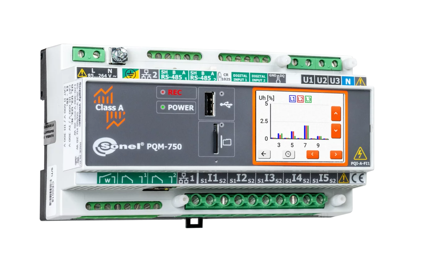
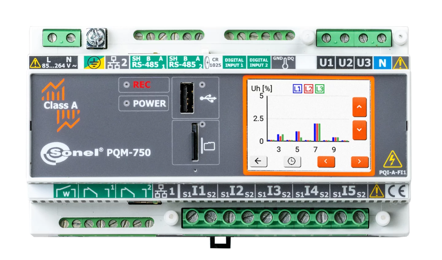
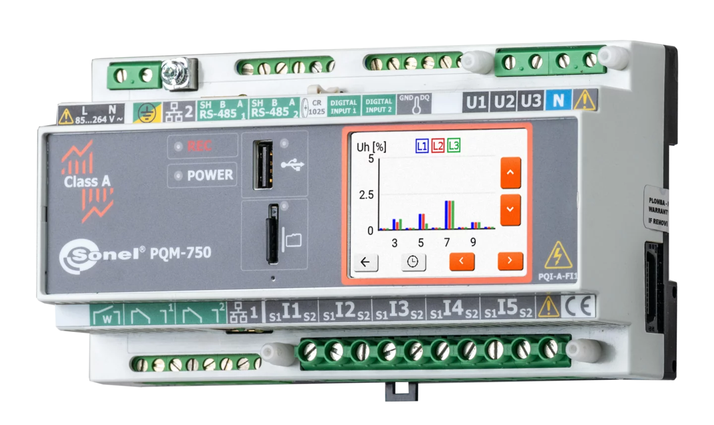
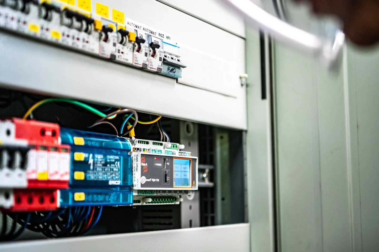
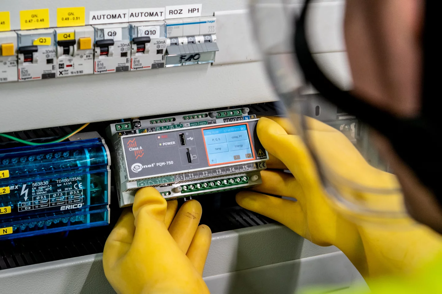
Stacjonarny miernik przeznaczony do pomiaru i rejestracji parametrów zasilania na zgodność z normami i obowiązującym prawem oraz z możliwością weryfikowania zadanych warunków kontraktu sprzedaż/zakup energii.
Wykonany w klasie A. Przystosowany do zamontowania na szynie DIN (z możliwością zamocowania na ścianie w szafie). Modułowa konstrukcja pozwala na dodawanie nowych modułów rozszerzających możliwości miernika. Przyrząd umożliwia pomiary w sieciach o częstotliwości 50 Hz, 60 Hz oraz 400 Hz.
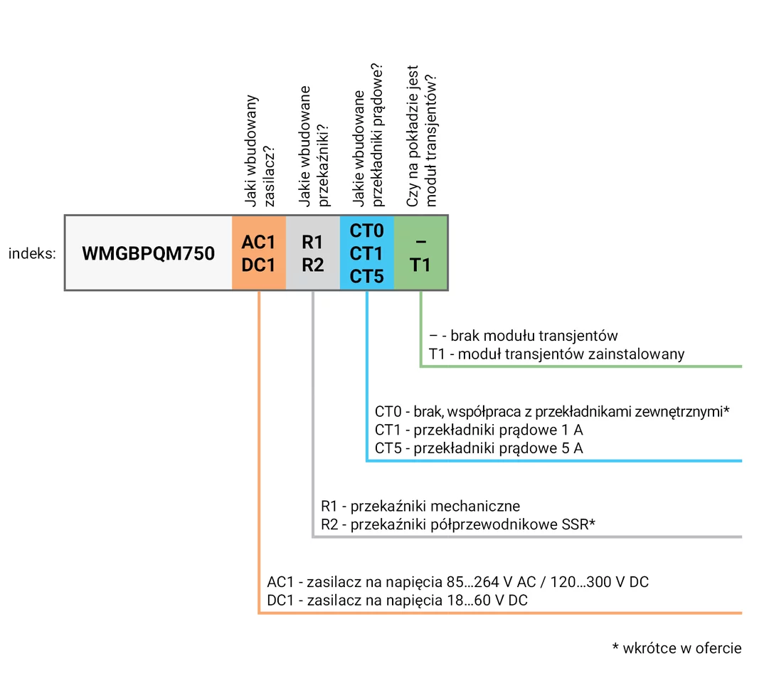
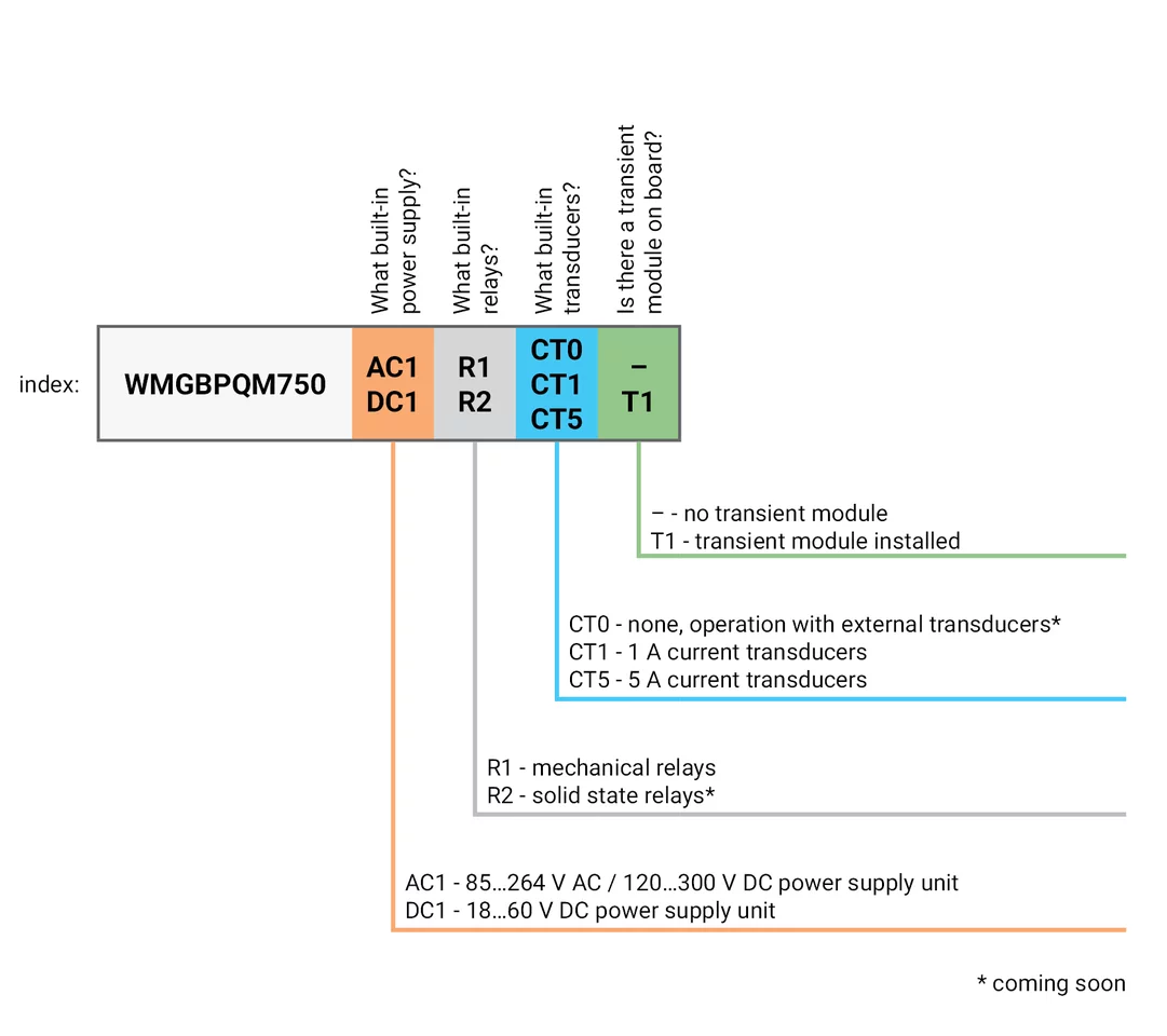
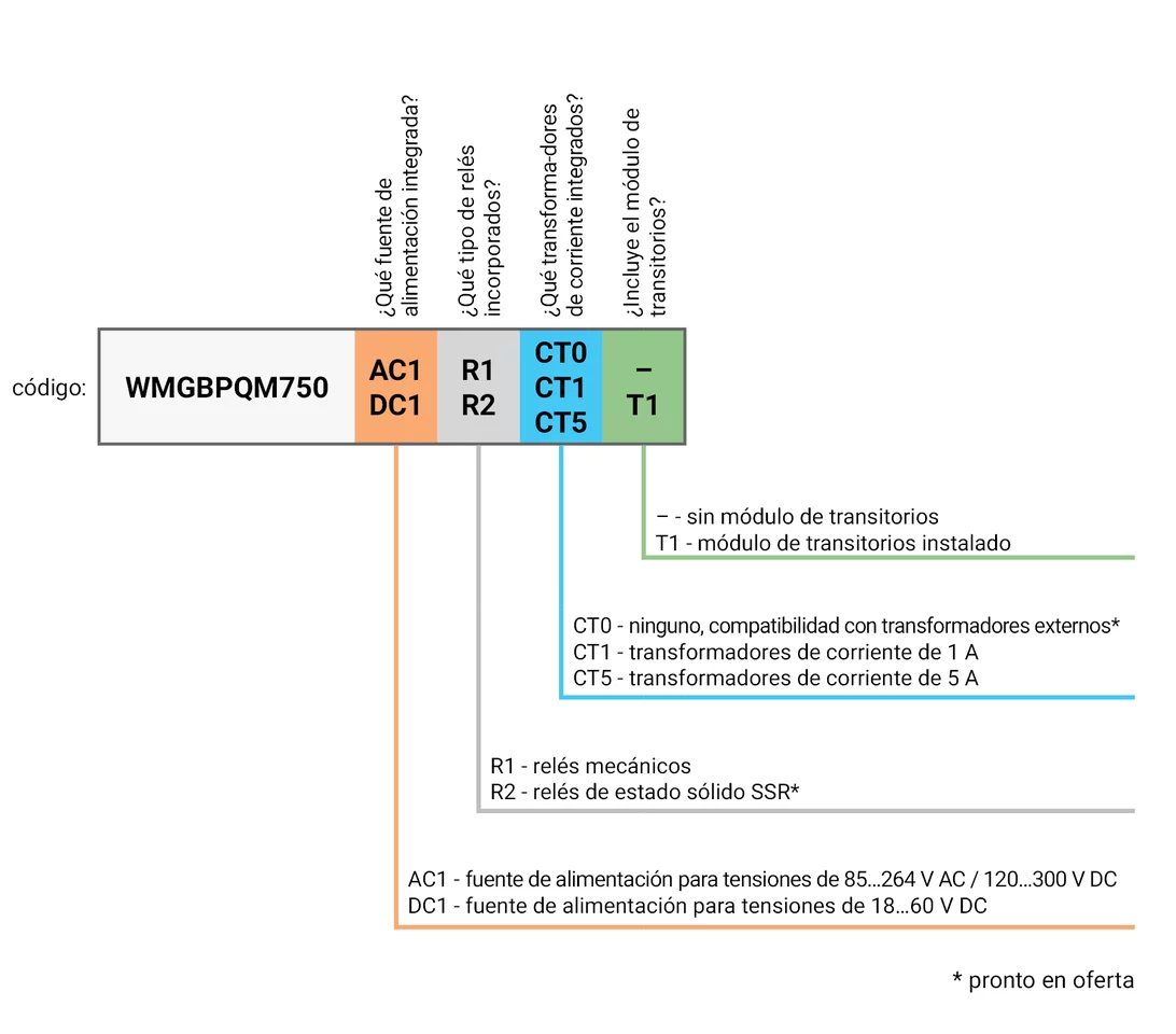
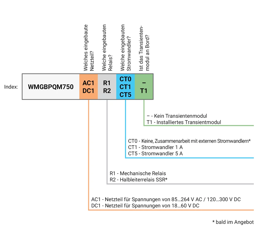
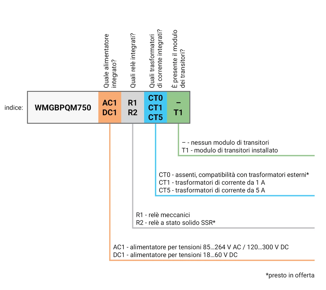
PQM-750 może być skonfigurowany na różne sposoby. Każdy zestaw wbudowanych modułów wewnętrznych to osobny indeks sprzedażowy analizatora. Potrzebujesz pomocy w wyborze konfiguracji? Skontaktuj się z naszym Biurem Obsługi Klienta.
|
Jaki wbudowany zasilacz? |
Jakie wbudowane przekaźniki? |
Jakie wbudowane przekładniki prądowe? |
Czy na pokładzie jest moduł transjentów? |
Indeks |
| AC1 - zasilacz na napięcia 85…264 V AC / 120…300 V DC |
R1 - przekaźniki mechaniczne | CT1 - przekładniki prądowe 1 A | Brak modułu transjentów | WMGBPQM750AC1R1CT1 |
| AC1 - zasilacz na napięcia 85…264 V AC / 120…300 V DC |
R1 - przekaźniki mechaniczne | CT1 - przekładniki prądowe 1 A | T1 - moduł transjentów zainstalowany | WMGBPQM750AC1R1CT1T1 |
| AC1 - zasilacz na napięcia 85…264 V AC / 120…300 V DC |
R1 - przekaźniki mechaniczne | CT5 - przekładniki prądowe 5 A | Brak modułu transjentów | WMGBPQM750AC1R1CT5 |
| AC1 - zasilacz na napięcia 85…264 V AC / 120…300 V DC |
R1 - przekaźniki mechaniczne | CT5 - przekładniki prądowe 5 A | T1 - moduł transjentów zainstalowany | WMGBPQM750AC1R1CT5T1 |
| DC1 - zasilacz na napięcia 18…60 V DC |
R1 - przekaźniki mechaniczne | CT1 - przekładniki prądowe 1 A | Brak modułu transjentów | WMGBPQM750DC1R1CT1 |
| DC1 - zasilacz na napięcia 18…60 V DC |
R1 - przekaźniki mechaniczne | CT1 - przekładniki prądowe 1 A | T1 - moduł transjentów zainstalowany | WMGBPQM750DC1R1CT1T1 |
| DC1 - zasilacz na napięcia 18…60 V DC |
R1 - przekaźniki mechaniczne | CT5 - przekładniki prądowe 5 A | Brak modułu transjentów | WMGBPQM750DC1R1CT5 |
| DC1 - zasilacz na napięcia 18…60 V DC |
R1 - przekaźniki mechaniczne | CT5 - przekładniki prądowe 5 A | T1 - moduł transjentów zainstalowany | WMGBPQM750DC1R1CT5T1 |
Cechy
- Pełna klasa A wg IEC 61000-4-30, potwierdzona certyfikatem z akredytowanego laboratorium
- Wejścia napięciowe L1, L2, L3, N, E (5 zacisków)
- Prądy L1, L2, L3, N, E (5 przekładników)
- Wbudowane przekładniki prądowe 5 A lub 1 A albo wariant bez przekładników, za to współpracujący z przekładnikami zewnętrznymi*
- Możliwość pomiarów pośrednich z wynikami obliczeń dla strony pierwotnej
- Praca w sieciach 50 Hz, 60 Hz, 400 Hz
- Rejestracja zdarzeń napięciowych i prądowych wraz z przebiegami
- Wykonanie z lub bez modułu pomiaru transjentów
- Pomiar ponad 4000 parametrów
- Przetwornik analogowo-cyfrowy 24-bitowy
- Podstawowa częstotliwość próbkowania 80 kHz
- Monitoring zaburzeń przewodzonych w paśmie 2…150 kHz
- Dwa porty LAN, w tym jeden z opcją zasilania miernika PoE (Power over Ethernet)
- Wbudowany akumulator
- Dwa warianty zasilania sieciowego: wbudowany zasilacz 85…264 V AC (120…300 V DC) lub 18…60 V DC
- Pamięć 8 GB (karta microSD)
- Port USB do aktualizacji miernika i wymiany danych
- Dwa wejścia binarne, dwa wyjścia przekaźnikowe, dwa porty RS-485
- Wyjście przekaźnikowe monitorujące pracę analizatora (Watchdog)
- Wejście 1-wire dla czujników temperatury zewnętrznej
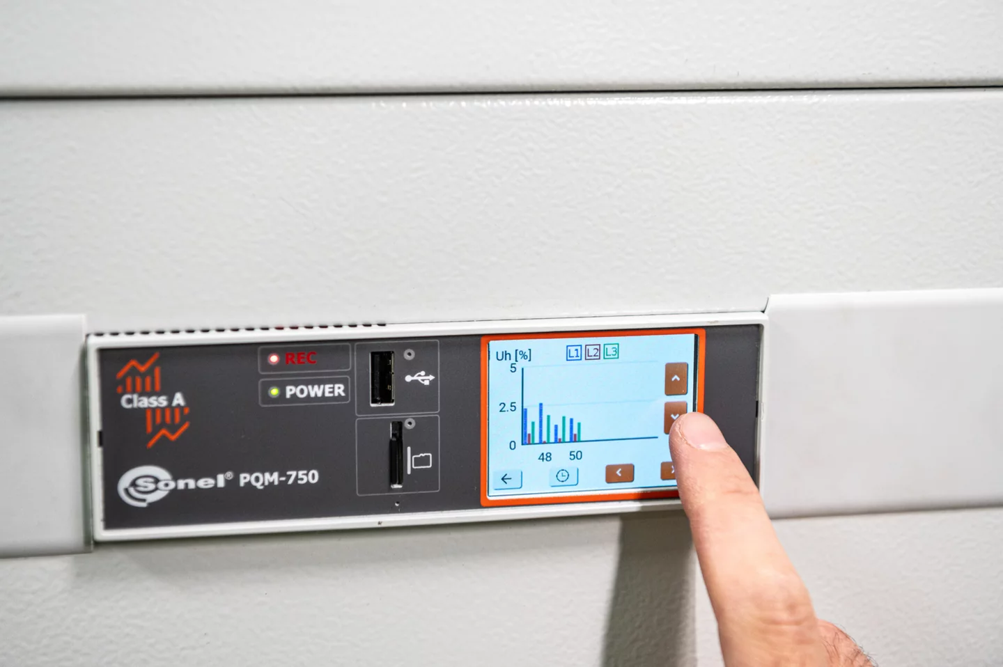
- Ekran dotykowy 2,4”
- Montaż na szynie DIN lub ścianie
- Szyna rozszerzeń umożliwiająca podłączenie różnych modułów zewnętrznych (np. GPS, LTE)
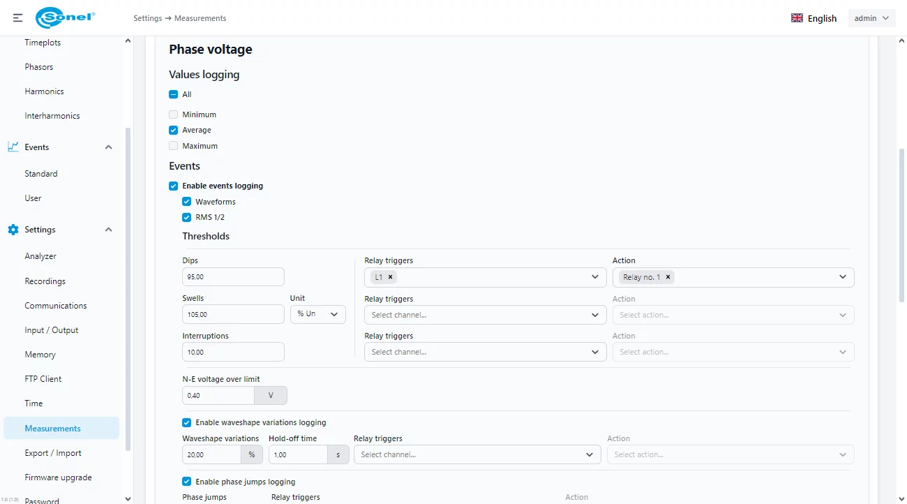
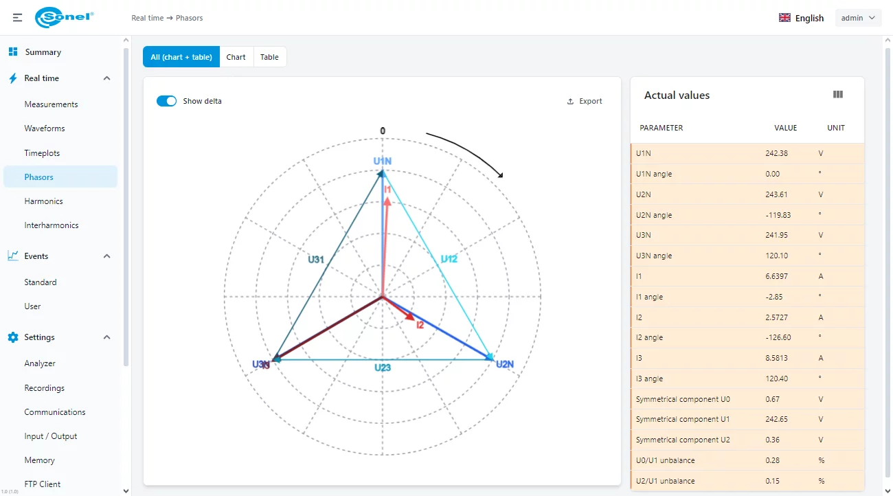
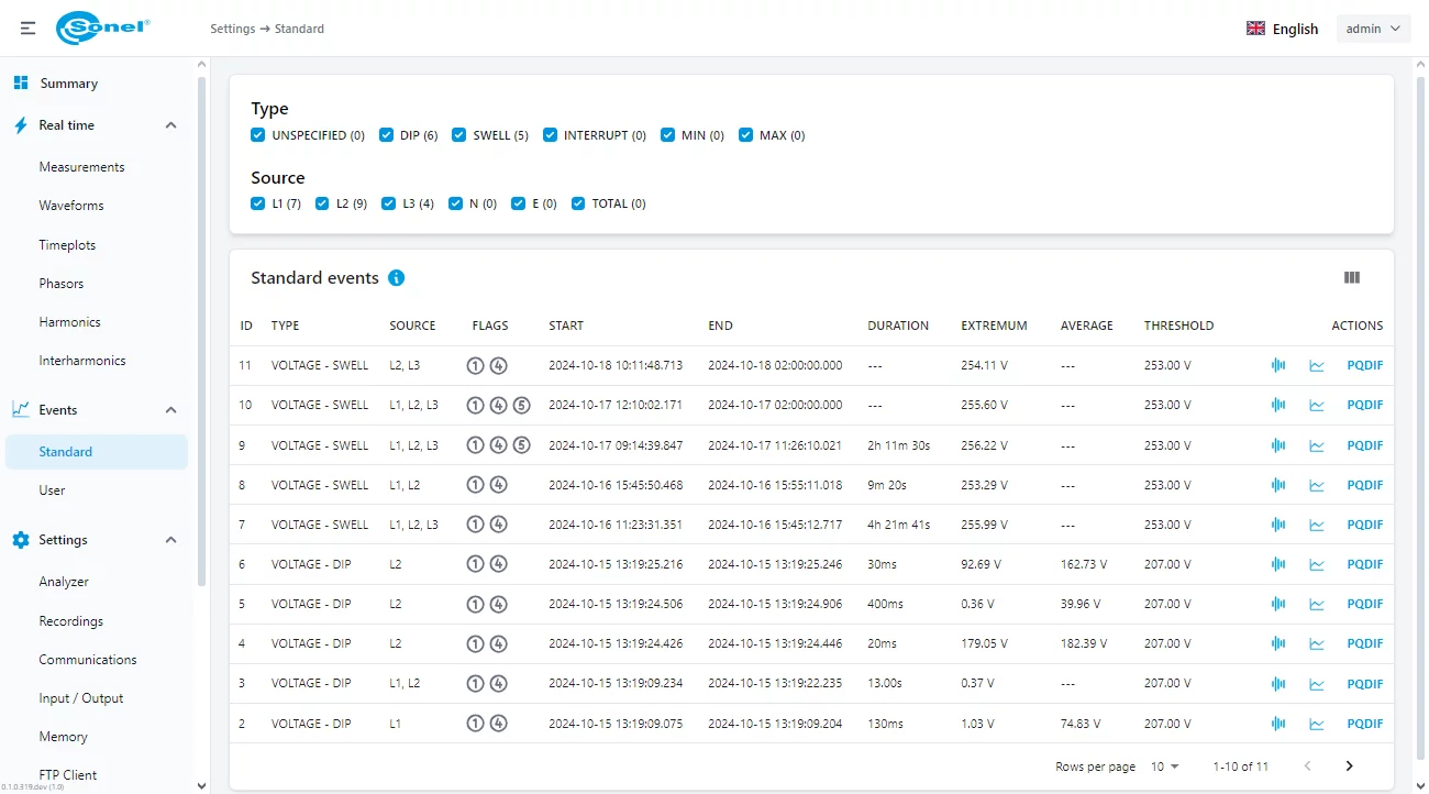
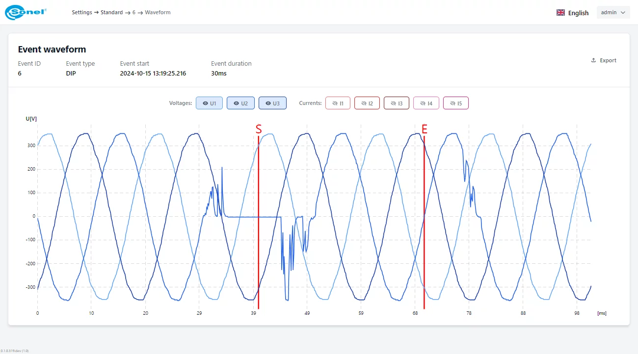
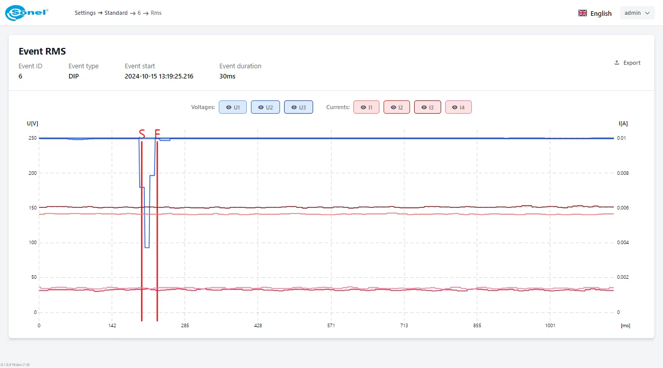
- Wbudowany serwer sieciowy, umożliwiający zaprogramowanie miernika, odczyt danych bieżących, podgląd listy zarejestrowanych zdarzeń wraz z wyświetleniem oscylogramu/RMS
- Synchronizacja czasu z wzorcem przez serwery NTP, IRIG-B (przez wbudowany RS-485)
- Opcjonalny moduł GPS i anteny GPS
- Kategoria pomiarowa CAT III 600 V (IV 300 V) dla wejść napięciowych
- Kategoria pomiarowa CAT III 300 V dla wejść prądowych
- Możliwość plombowania wejść prądowych i napięciowych
* wkrótce w ofercie
Cechy dodatkowe
Standardowe protokoły transmisyjne
- Modbus TCP/IP
- Modbus RTU
- IEC 61850
- PQdif
Interfejs sieciowy (webserwer)
- Dostęp do interfejsu z dowolnej przeglądarki internetowej
Modułowość
Przyrząd można rozbudować o dodatkowe protokoły komunikacyjne oraz funkcjonalności fizyczne i programowe.
- Moduł GPS z wyjściem IRIG-B i antena do modułu GPS (10 m / 20 m / 30 m)
- Moduł LTE GSM*
- Moduł I/O*
- Panel dotykowy LCD 7” do pełnej obsługi analizatora w miejscu zamontowania*
* wkrótce w ofercie
Mierzone parametry
Wbudowane oprogramowanie (interfejs sieciowy – webserwer) pozwala skonfigurować przyrząd oraz podejrzeć dane bieżące. Umożliwia pomiar poniższych parametrów.
- Napięcie fazowe skuteczne U dla L1, L2, L3+N/PE
- Napięcia międzyfazowe skuteczne U dla L12, L23, L31
- Prądy skuteczne I wszystkich faz + N + PE
- Współczynnik szczytu CF napięć i prądów
- Częstotliwość f sieci L1
- Moc czynna P dla L1, L2, L3
- Moc czynna P1 (wydzielona 50 Hz) dla L1, L2, L3
- Moc bierna Q dla L1, L2, L3
- Moc bierna Q1 (wydzielona 50 Hz) dla L1, L2, L3
- Moc pozorna S dla L1, L2, L3
- Moc pozorna S1 (wydzielona 50 Hz) dla L1, L2, L3
- Moc całkowita trójfazowa P3F, Q3F, S3F
- Moc całkowita trójfazowa P13F, Q13F, S13F
- cosφ dla L1, L2, L3, cosφ3F
- Współczynnik mocy PF dla L1, L2, L3, PF3F
- tgφ dla L1, L2, L3, tgφ3F
- Moc odkształceń D dla L1, L2, L3
- Moc całkowita odkształceń trójfazowa D3F
- Współczynnik mocy odkształceń DPF dla L1, L2, L3
- Kształt napięć i prądów fazowych dla zdarzeń
- Wykresy fazowe dla prądów i napięć
- Energia czynna dla L1, L2, L3 – pobrana EP+ lub oddana EP-
- Energia czynna trójfazowa – pobrana EP3F+ lub oddana EP3F-
- Energia bierna indukcyjna dla L1, L2, L3 dla poboru – EQL+
- Energia bierna pojemnościowa dla L1, L2, L3 dla poboru – EQC+
- Energia bierna trójfazowa dla poboru – indukcyjna EQL3F+ i pojemnościowa EQC3F+
- Energia pozorna dla L1, L2, L3 – ES
- Energia pozorna trójfazowa ES3F
- Harmoniczne hn do 256-tej w prądzie i napięciu
- Interharmoniczne do 256-tej w prądzie i napięciu
- Kąty pomiędzy harmonicznymi prądu i napięcia
- Monitorowanie pasma 2…150 kHz
- Składowe napięć fazowych UDC
- Udziały harmonicznych prądów i napięć względem wartości RMS (%) – hnR
- Udziały harmonicznych prądów i napięć względem harmonicznej podstawowej h1 (%) – hnF
- THDR dla napięć i prądów liczone względem wartości RMS (%)
- THDF dla napięć i prądów liczone względem harmonicznej podstawowej (%)
- TIDR dla napięć i prądów liczone względem wartości RMS (%)
- TIDF dla napięć i prądów liczone względem harmonicznej podstawowej (%)
- Moce czynne i bierne harmonicznych
- Współczynnik K dla I1, I2, I3, IN
- Współczynnik (Europa) Factor K
- Składowe symetryczne napięcia: zerowa U0, zgodna U1, przeciwna U2
- Wartości napięć (V, %) składowych harmonicznych kolejności zgodnej (1, 4, 7,…), przeciwnej (2, 5, 8,…), zerowej (3, 6, 9,…)
- Składowe symetryczne prądu: zerowa I0, zgodna I1, przeciwna I2
- Wartości prądów (A, %) składowych harmonicznych kolejności zgodnej (1, 4, 7,…), przeciwnej (2, 5, 8,…), zerowej (3, 6, 9,…)
- Współczynnik migotania światła krótkotrwały Pst
- Współczynnik migotania światła długotrwały Plt
- Współczynnik asymetrii napięć
- Współczynnik asymetrii prądów
- Transjenty U do 6000 V
- Sygnały sterujące
- Temperatury: Tw (wewnętrzna analizatora), Tz1…Tz4 (1-wire)
Normy
Przyrząd wykonany w klasie A normy IEC 61000-4-30. Przyrząd jest zgodny z:
- Normy dotyczące produktów:
- IEC 62586-1 – Pomiar jakości energii elektrycznej w sieciach zasilających – Część 1: Przyrządy do pomiaru jakości energii (PQI)
- IEC 62586-2 – Pomiar jakości energii elektrycznej w sieciach zasilających – Część 2: Badania funkcjonalne oraz wymagania dotyczące niepewności
- Normy dotyczące pomiaru parametrów sieci:
- IEC 61000-4-30 – Kompatybilność elektromagnetyczna (EMC) – Metody badań i pomiarów – Metody pomiaru jakości energii
- IEC 61000-4-7 – Kompatybilność elektromagnetyczna (EMC) – Metody badań i pomiarów – Ogólny przewodnik dotyczący pomiarów harmonicznych i interharmonicznych oraz stosowanych do tego celu przyrządów pomiarowych dla sieci zasilających i przyłączonych do nich urządzeń
- IEC 61000-4-15 – Kompatybilność elektromagnetyczna (EMC) – Metody badań i pomiarów – Miernik migotania światła – Specyfikacja funkcjonalna i projektowa
- EN 50160 – Parametry napięcia zasilającego w publicznych sieciach rozdzielczych
- Normy bezpieczeństwa:
- IEC 61010-1 – Wymagania bezpieczeństwa dotyczące elektrycznych przyrządów pomiarowych, automatyki i urządzeń laboratoryjnych – Część 1: Wymagania ogólne
- IEC 61010-2-030 – Wymagania bezpieczeństwa dotyczące elektrycznych przyrządów pomiarowych, automatyki i urządzeń laboratoryjnych – Część 2-030: Wymagania szczegółowe dotyczące urządzeń zawierających obwody badawcze lub pomiarowe
- Normy dotyczące kompatybilności elektromagnetycznej:
- EN 55032 – Kompatybilność elektromagnetyczna urządzeń multimedialnych – Wymagania dotyczące emisji
- IEC 61000-6-5 – Kompatybilność elektromagnetyczna (EMC) – Część 6-5: Normy ogólne – Odporność urządzeń wykorzystywanych w środowisku elektrowni i stacji elektroenergetycznej
