


| Parameter | Description |
|---|---|
| Basic technical data | |
| RCD type | 30 mA type AC |
| Power supply | 230 V network |
| Power consumption | ca. 15 mW |
| Protection | 2 x T3 14 A 250 V or 2 x F 4 A 250 V |
| Safety and work conditions | None |
| Measuring category according to EN 61010 | II 300 V |
| Ingress protection | IP40 |
| Type of insulation according to EN 61010-1 and IEC 61557 | single |
| Operating temperature | 10…+40°C |
| Storage temperature | -20…+60°C |
| Humidity | 20…80% |
0
Login

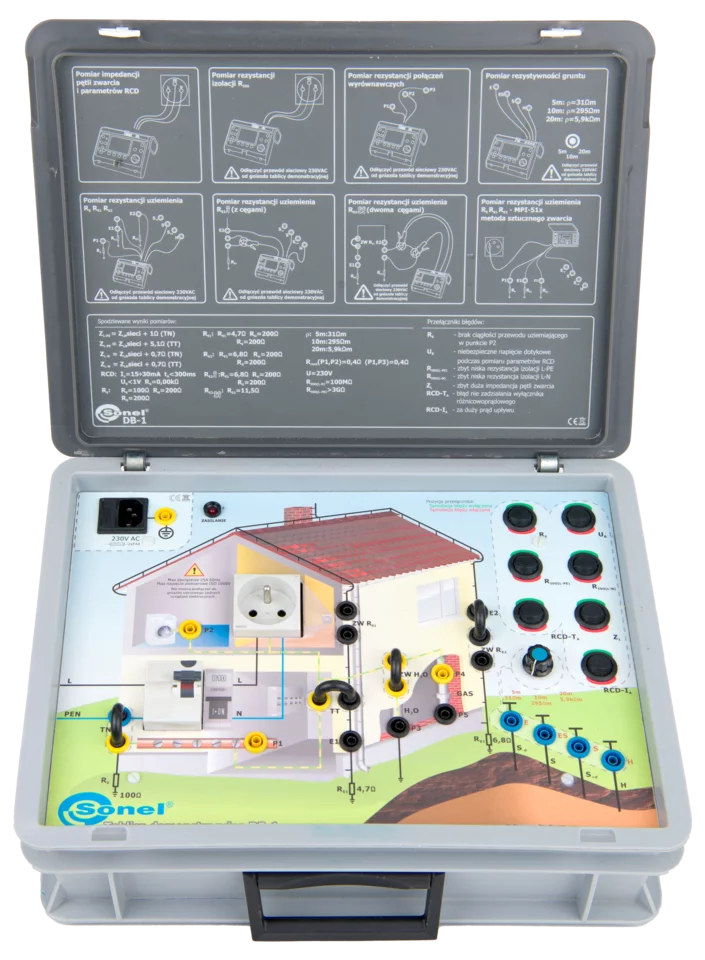
Training in electrical installations
The Sonel DB-1 board enables simulation of electrical measurements and faults and abnormalities in circuits. It enables the presentation of measurements of short circuit loop impedance, RCD parameters, insulation resistance, continuity of protective and equalising connections. A unique feature is the ability to present earthing measurements using the technical methods (3p, 4p), the technical method with clamps, the two-clamp method, as well as using the instrument for measuring short-circuit loops.
For each measurement it is possible to simulate different operating conditions and show typical errors and irregularities occurring in real consumer installations. The design of Sonel DB-1 enables its use in any place provided it is supplied with 230V. All measurements carried out with DB-1 do not interfere in any way with the installation to which the demonstration board will be connected.
Features
The DB-1 board makes it possible to demonstrate the method of performing the following tests:
- fault loop impedance for assessment of the automatic power cutoff condition,
- RCD parameters,
- earthing resistance,
- soil resistivity,
- continuity test of equipotential bonding,
- insulation resistance,
- power network voltage.
It is possible to simulate typical failures and irregularities in the electrical network.
Measurements
Technical specifications of DB-1 board and features of individual functions:
- Fault loop impedance:
- measurement of L-N short-circuit with impulse currents up to 25 A and 60 ms,
- measurement of L-PE earth fault loop with impulse currents up to 20 mA.
- RCD parameters (30 mA RCD):
- measurement of RCD trip time,
- measurement of RCD trip current,
- earth resistance measurement,
- touch voltage measurement.
- Soil resistivity:
- esistivity measurement for three soil types (31 Ωm, 295 Ωm, 5.9 kΩm
- Earthing resistance. Measurement by method:
- 2-pole method,
- 3-pole method,
- 4-wire method,
- 3-pole method with clamp,
- two-clamp method,
- with the use of fault loop meter.
- Continuity of connections:
- measurement of equipotential bonding and connections of accessible parts.
- Insulation resistance:
- measurement of L-N insulation,
- measurement of L-PE insulation,
- measurement of N-PE insulation.
- Voltage measurement:
- voltage measurement in power socket.
- Simulation of irregularities:
- no continuity of earth conductor (RE ),
- safe voltage exceeded during RCD measurement (UB),
- permissible RCD tripping current (IA) exceeded,
- permissible RCD tripping time (tA) exceeded,
- insufficient L-N insulation resistance (RISO(L-N)),
- insufficient L-PE insulation resistance (RISO(L-PE)),
- excessive fault loop impedance (ZL).
- 230 V network socket.
| Parameter | Value |
|---|---|
| Net weight (kg) | 3.8 |
| Package weight (kg) | 4.4 |
| Package width (cm) | 14.2 |
| Package height (cm) | 34.6 |
| Package length (cm) | 42.2 |
Accessories included with the meter
Files to download


© 2026 Sonel
